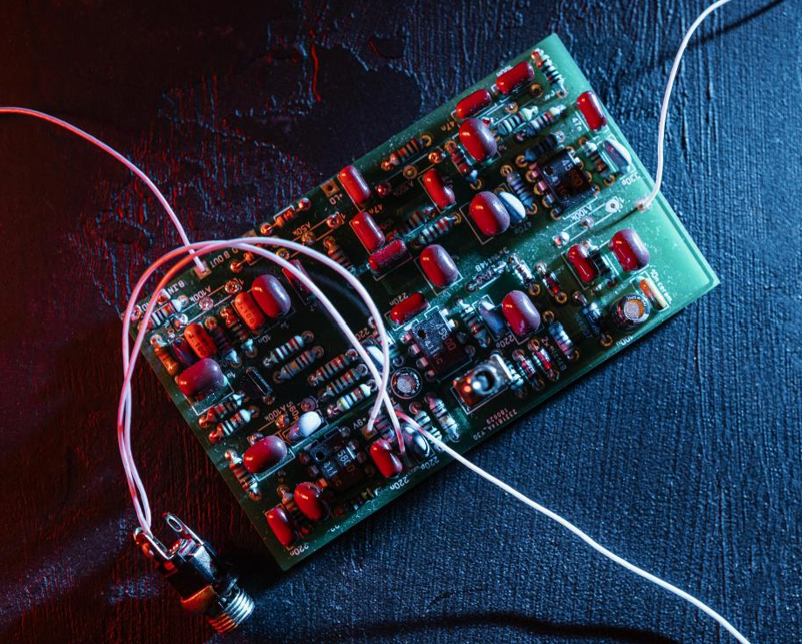
How to Test a Varistor?: All You Want to Know
What is a Varistor?
A varistor, also known as a voltage-dependent resistor (VDR), has a nonlinear current-voltage relationship, which means that its resistance lowers as the applied voltage increases. Typically made up of a ceramic mass of zinc oxide (ZnO) grains placed between two metal plates, the borders between these grains form diode junctions.
At low voltages, the varistor has a high resistance, similar to an open switch; but, if the voltage above a certain threshold, its resistance reduces dramatically, allowing current to flow as a closed switch. This clamping action keeps voltage surges at a reasonably constant value, protecting downstream circuits. The varistor's current-voltage curve is extremely nonlinear, with high resistance at low voltages and low resistance at high voltages. As a reliable electronic components distributor, Ersa Electronics will provide all kinds of original chips for your inquiry.
Key Characteristics of Varistor
The resistance of a voltage-dependent resistor fluctuates nonlinearly with the applied voltage. Under normal load conditions, the impedance is high; but, when a voltage threshold, or breakdown voltage, is exceeded, the impedance rapidly lowers to a low level. They are widely used to protect circuits against large transient voltages. When the circuit encounters a high voltage transient, the varistor begins to conduct and clamps the transient voltage to a safe level. The circuit is protected from the incoming surge's energy by partial conductance and partial absorption.
The MOV, or metal oxide varistor, is the most commonly used kind. Zinc oxide (ZnO) grains are sintered into a matrix to create the structure. Similar to a diode junction, the grain boundaries provide P-N junction semiconductor characteristics. A huge network of parallel and series diodes can be compared to a matrix of randomly arranged grains. When a low voltage is provided, little current flows because to reverse leakage via the connections. A large current can flow through the junctions, but only if a high voltage greater than the breakdown voltage is applied. This behavior is referred to as avalanche collapse. This behavior produces nonlinear current-voltage characteristics.
The following broadly describes the relationship between the voltage (V) across the terminals and the current (I) through them:
What Does a Varistor Do?
A varistor, specifically a Metal Oxide Varistor (MOV), is a critical electrical component used largely for overvoltage protection in circuits. Its major function is to protect sensitive electronic equipment from voltage spikes by adjusting resistance in response to the applied voltage.
How Varistors Work:
Voltage-Dependent Resistance:
A varistor has a nonlinear resistance that lowers dramatically when the voltage across it surpasses a certain threshold known as the clamping voltage. This enables it to conduct huge quantities of current when subjected to overvoltage situations, thereby diverting excess voltage away from the protected circuit.
Parallel Configuration:
Varistors are commonly wired in parallel with the loads they safeguard. When a voltage spike occurs, the varistor's resistance decreases, allowing current to be drawn away from the load. This action prevents damage to delicate components by redirecting excess energy.
Fuse Coordination:
In most cases, varistors are utilized in conjunction with fuses. The varistor will conduct during a voltage spike, increasing current flow until the fuse trips if the overvoltage condition persists. This combination ensures that, while the varistor absorbs transient spikes, the fuse serves as the final line of protection against prolonged overcurrent conditions.
Applications:
Surge Protection: Varistors are widely employed in surge protection devices (SPDs) for both residential and industrial purposes. They help to protect electrical equipment from lightning strikes and other transient voltage spikes that can occur in power lines.
Electronics and appliances: Many electronic equipment use varistors to protect against voltage spikes that may occur during operation or as a result of external causes such as power grid disturbances.
Limitations: Varistors degrade over time when exposed to high-energy transients. They are regarded as sacrificial devices; after absorbing many high-voltage spikes, they may fail and require replacement.
Not for Continuous Overvoltage: While varistors are effective for transient surges, they are not intended to manage continuous overvoltage. If sustained high voltage is applied, they may fail without appropriately safeguarding downstream components.
In conclusion, varistors serve an important role in shielding electronic circuits from voltage spikes by providing a low-resistance channel during overvoltage conditions, reducing damage to sensitive components.
What is a Varistor used for?
Varistors, also known as Voltage Dependent Resistors (VDRs), are critical components in electrical circuits that are primarily employed to prevent transient overvoltage. Because of their voltage-dependent resistance, which allows them to absorb excess energy during voltage spikes, they protect sensitive electronic components from harm. Varistors are mostly used for the following purposes:
Surge Protection: Surge protection systems typically use varistors to avoid high voltage spikes caused by lightning strikes, power surges, or other electrical interruptions. By limiting the voltage to a safe level, they protect linked equipment.
Electrical Circuit Protection: Varistors prevent overvoltage in both AC and DC circuits. To provide total protection against voltage transients, they could be connected across phases or across main supplies.
Industrial Equipment: Varistor protection is critical in industrial automation because it protects motors and other inductive loads from high-voltage surges caused when these devices are turned off. They help to protect switches and other components by absorbing the counter-electromotive force created during operation.
Consumer Electronics: Varistors are used in consumer electronics and household appliances to ensure the reliability of sensitive circuits, regulate noise, and prevent overvoltage. They are typically seen in wall outlets and power strips that have surge protection.
Medical Devices: Varistors safeguard sensitive monitoring components in medical equipment such as ECG and EEG units from electrical noise and surges, ensuring accurate findings and patient safety.
Power Supply Systems: Varistors are used in power supply circuits to prevent transient voltages caused by switching operations or external disturbances. They often perform best when paired with EMC filters to improve overall power supply reliability.
Telecommunication Systems: Varistors have long been used in communication systems to decrease noise and voltage spikes, allowing for clear signal transmission and protecting customers from loud noises caused by sudden circuit switching.
What is the Principle of Varistor Resistor?
1. The voltage V1mA is pressure-sensitive
When the power supply voltage is constantly applied to both ends of the varistor, the "maximum continuous working voltage" amount provided in the specification cannot be exceeded. For a 220V AC power supply with pressure-sensitive selection, the varistor's maximum DC working voltage must exceed the power line's DC working voltage (VIN), or VDC ≥ VIN. This allows for an acceptable margin when determining the varistor's pressure-sensitive voltage value, fully accounting for grid working voltage changes. The household electricity grid fluctuates by about 25% on average. A voltage-sensitive resistor with a voltage between 470 and 620 volts might be a better choice. Choosing a varistor with a higher voltage yields a little higher residual voltage but a reduced failure rate and a longer service life.
2. The choice of flux flow
The maximum surge current that could occur while the device is operational, or the required surge current, should exceed the varistor's nominal discharge current. To calculate the nominal discharge current, consider the number of surge life quotas of the pressure-sensitive resistor curve in the impact that are more than ten times the value, or nearly 30% of the maximum impact flux (i.e., 0.3IP).
3. Clamping Voltage Selection
The clamping voltage of the varistor must be less than the maximum voltage (also known as the safety voltage) that the protected equipment or part can withstand.
4. Selection of capacitance Cp
High-frequency transmission signals should have a lower capacitance (Cp), and vice versa.
5. Resistance Match
Varistor has transitory internal resistance. To safeguard components with low internal resistance, use a high capacitance varistor without affecting signal transmission rate (R ≥ 5Rv). Internal resistance of protected components (line) is greater than 2Ω.
How Does a varistor Work?
A varistor, also known as a voltage-dependent resistor (VDR), is an electrical component with nonlinear resistance that changes depending on the voltage placed across it. This distinguishing feature enables varistors to safeguard circuits from voltage spikes or transients.
Resistant Behavior
Low Voltage Condition: When the voltage across the varistor falls below a certain threshold (known as the varistor voltage), it operates like an open switch, with extremely high resistance (essentially infinite). In this state, only a small current travels through it.
High Voltage Condition: When the voltage crosses this threshold, the resistance falls considerably, enabling a high current to pass through. This behavior is similar to a closed switch. The varistor effectively clamps the voltage to a relatively constant value, protecting downstream components from high voltages.
Principle of Operation
The operation of a varistor can be understood as follows:
When the voltage applied to the varistor is less than its threshold voltage, the current flowing through it is exceedingly low, similar to a resistor with infinite resistance. This indicates that the varistor is in an open state.
When the voltage applied to the varistor reaches its threshold, the current through it surges and it behaves like a resistor with endlessly low resistance. In this state, the varistor is the same as a closed switch.
Because of this operating principle, the varistor operates as a switch, closing only when the voltage exceeds the threshold, resulting in a surge in the current flowing through it. This protects other circuit components by reducing the effect of overvoltage on succeeding sensitive circuits.
Response Time
Varistors typically have a response time of less than 25 nanoseconds. This quick response enables them to successfully clamp voltage spikes and safeguard delicate electrical components.
In summary, a varistor's peculiar resistance characteristic, which varies substantially depending on the applied voltage, allows it to effectively defend against voltage transients in electronic circuits.
How to Test a Varistor?
1. Preparing before measuring the varistor.
Connect the resistor's positive and negative test lines to determine its true resistance value. To improve measurement accuracy, the range is determined by the nominal value of the measured resistance. Because of the non-linear relationship, the midpoint of the ohm scale is acceptable. As a result, the pointer value should be as close to the scale's center as possible, or between 20% and 80% of the total radian. The reading and nominal resistance can differ by ± 5%, ± 10%, or ± 20%, depending on the resistance error level. When the error range is exceeded, the resistor alters the standard value.
2. How do you determine the quality of a varistor?
A power source with a wide regulating voltage range and good current limiting ability is often required to evaluate the varistor. When measuring, a precision voltmeter is connected in parallel with the varistor. Connect the variable power lead to the varistor's two ends.
The voltmeter displays the voltage generated by the power source. After reaching a certain level, gently adjust the voltage and see that it drops abruptly. The varistor's protection value is the voltage right before the decline.
A steady voltage can cause the varistor's resistance value to change from MΩ (Megohm) to mΩ (Milliohm). When the voltage is increased again, the varistor enters the saturation region and exhibits an extremely low linear resistance. When the voltage is low, the varistor functions in the leakage current area, resulting in high resistance and low leakage current. When the voltage rises into the nonlinear area, the current varies across a wide range while the voltage does not vary significantly. The varistor may eventually burn or rupture owing to overheating induced by the excessive current.
3. Selecting the varistor
The particulars of the circuit must be considered while selecting a varistor, however in general, the following rules should be followed:
(1) Select the varistor voltage V1mA.
The power source voltage that is constantly applied across the varistor must not exceed the "maximum continuous operating voltage" value provided in the specification, depending on how the power supply voltage is selected. In other words, the varistor's maximum DC operating voltage must be greater than the power line's (signal line's) DC operating voltage, or VDC > VIN. When selecting a 220V AC power source, consider the power grid's operating voltage fluctuation range. The household electricity grid fluctuates by about 25% on average. It is advisable to select a varistor with a voltage range of 470-620 volts. Although the residual voltage is slightly increased, using a varistor with a higher varistor voltage can reduce failure rates and extend service life.
(2) Choice of traffic
When operating equipment, the varistor's nominal discharge current should be greater than the maximum possible surge current or the surge current that can be tolerated. The nominal discharge current can be calculated by pressing the value of more than 10 shocks into the rating curve of surging life times—roughly 30% of the maximum shock flux, or 0.3 IP.
Selecting the clamping voltage.
The clamping voltage of the varistor should be less than the maximum voltage—also known as the safe voltage—that the equipment or component it protects can withstand.
(4) The selection of capacitor Cp
For high-frequency transmission signals, the capacitance Cp should be reduced; vice versa.
(5) Internal resistance matching (also known as Resistance Match)
The protected component's internal resistance (R≥2Ω) and the varistor's transient internal resistance (Rv) are connected as follows: R≥5Rv. If the protected component has a low internal resistance, you should try using a big capacitor varistor without affecting signal transmission rate.